Why another printer?
I have ten Bambu printers, including an H2S and H2C. I've spent plenty of time printing PET-CF, PA6-CF, PA12-CF, PPA-CF and PPS-CF on them. What sent me looking for something else was wanting more from those materials: stronger parts, larger geometries, and less designing around what will warp.
I've been disappointed by the strength of some engineering-filament parts that I expected much more from. A material can be printable without giving me the properties that made me choose it. The chamber is the part of the machine I want to change most.
Carbon fibre helps make difficult polymers more manageable, but I don't always want the trade in toughness that comes with a filled material. Sometimes I want unfilled nylon. Sometimes I want PC. I want to choose the polymer for the job, rather than reach for a CF version because it's easier to keep flat. A larger PA, PPA or PPS part shouldn't have to become a different design just to survive printing.
Buy the printer, or build on one?
The Vision Miner 22 IDEX was the commercial machine I kept coming back to. Its 100°C chamber, 200°C bed and 500°C hotends put it in the territory I was interested in, with an open material system and a second extruder for support. It was a useful picture of what I wanted, at a price I wanted to get well underneath.
I've built CNC machines from scratch, including AC-servo machines, so replacing controls and adapting a toolhead is an appealing project in its own right. Building a well-insulated oven, a rigid motion system and a thermal barrier between the two is a lot of work before getting to the interesting modifications. Used industrial printers offer a way to buy that engineering already assembled.
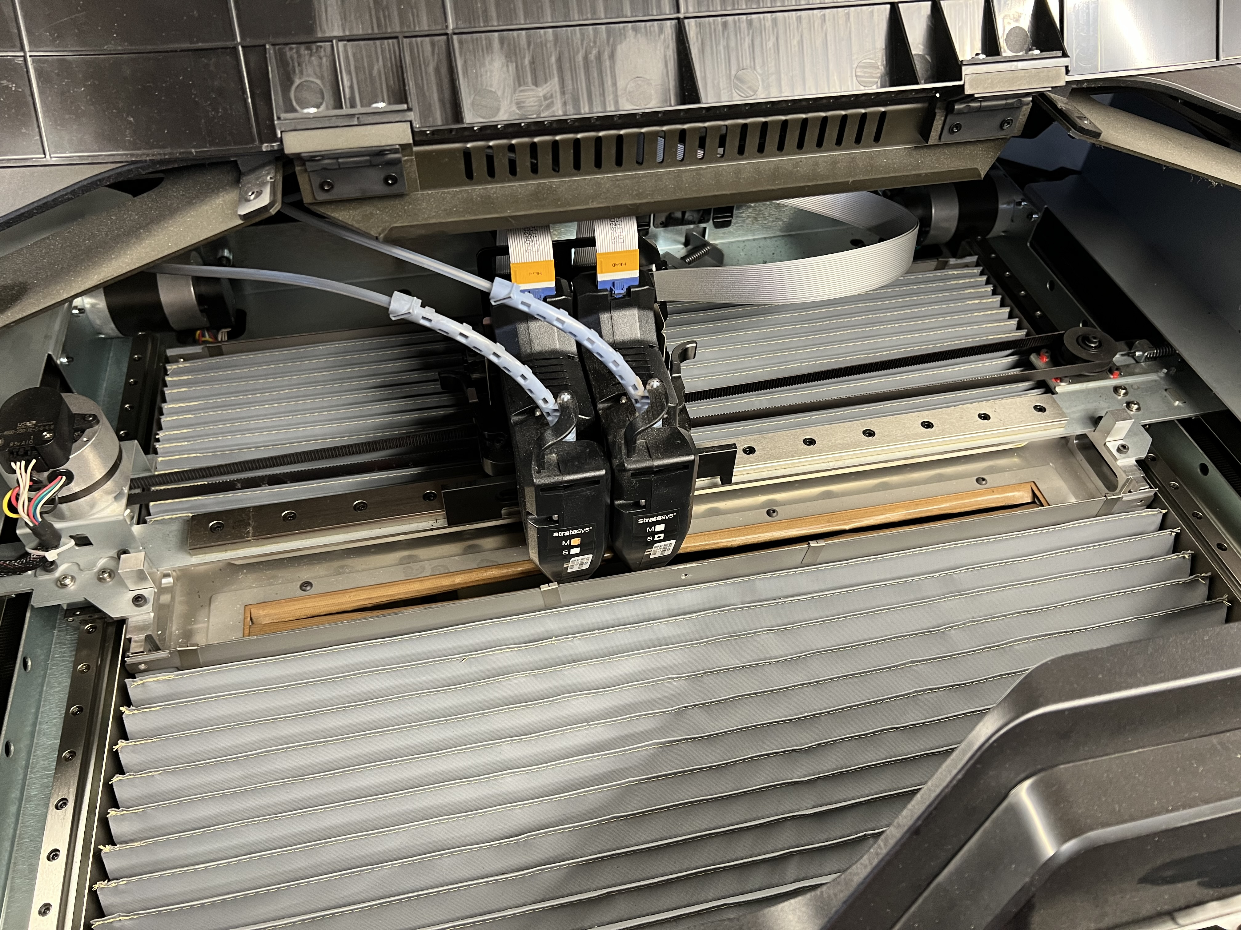
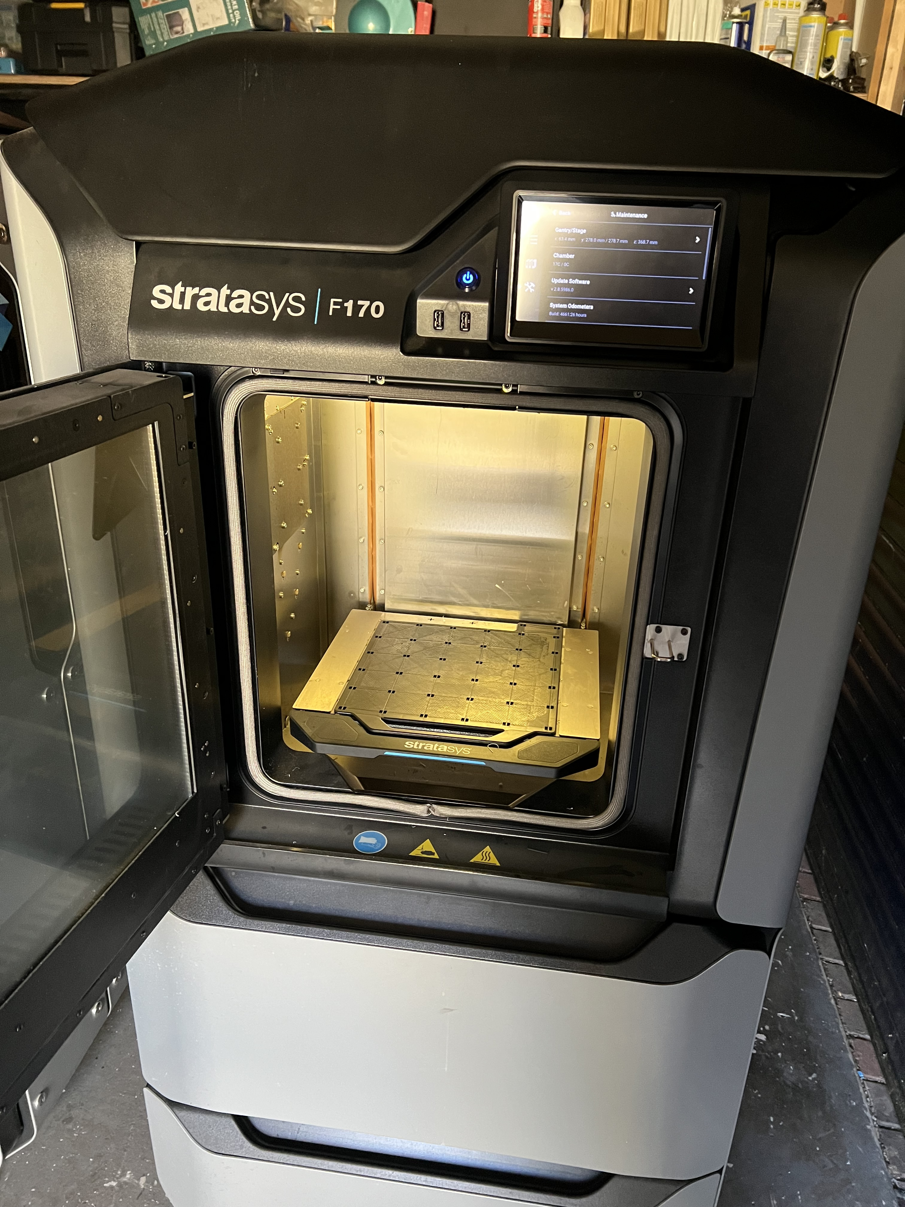
I looked at the older Stratasys Dimension Elite and the F123 machines. The F170 caught my attention because the motion system lives above the chamber, behind a sliding steel heat shield. Think CNC way covers forming the ceiling of an oven. The hotends reach through it; the gantry doesn't have to live in the same heat as the print.
Why are machines like this so cheap?
The original Stratasys ecosystem is part of the answer, to my mind. These are substantial machines tied to proprietary heads, material handling and software. The F123 spools even have memory chips; putting a generic reel in the drawer isn't the normal workflow. That is a very different proposition from buying a modern desktop printer and feeding it whatever filament you fancy.
For a conversion, the valuable bits are underneath that ecosystem: the insulated oven, metal chamber, linear motion, servo motors and serviceable mechanical assemblies. I want ordinary slicers, open controls and my choice of extrusion hardware on top of that foundation. The parts that make an old industrial machine awkward to own are largely the parts I intend to replace.
There was also an F370 available at £3,000, against £1,200 for the F170. Looking at the two listings, the gantry and chamber looked remarkably alike. My subsequent research pointed to the same kinematics, with the F170's travel restricted in software. Paying another £1,800 for the larger model made little sense for what I had in mind.
And then there were two.
I bought the working F170 for £1,200, with spare heads and material. A second one with a heater fault came along for £50. That was hard to leave behind.
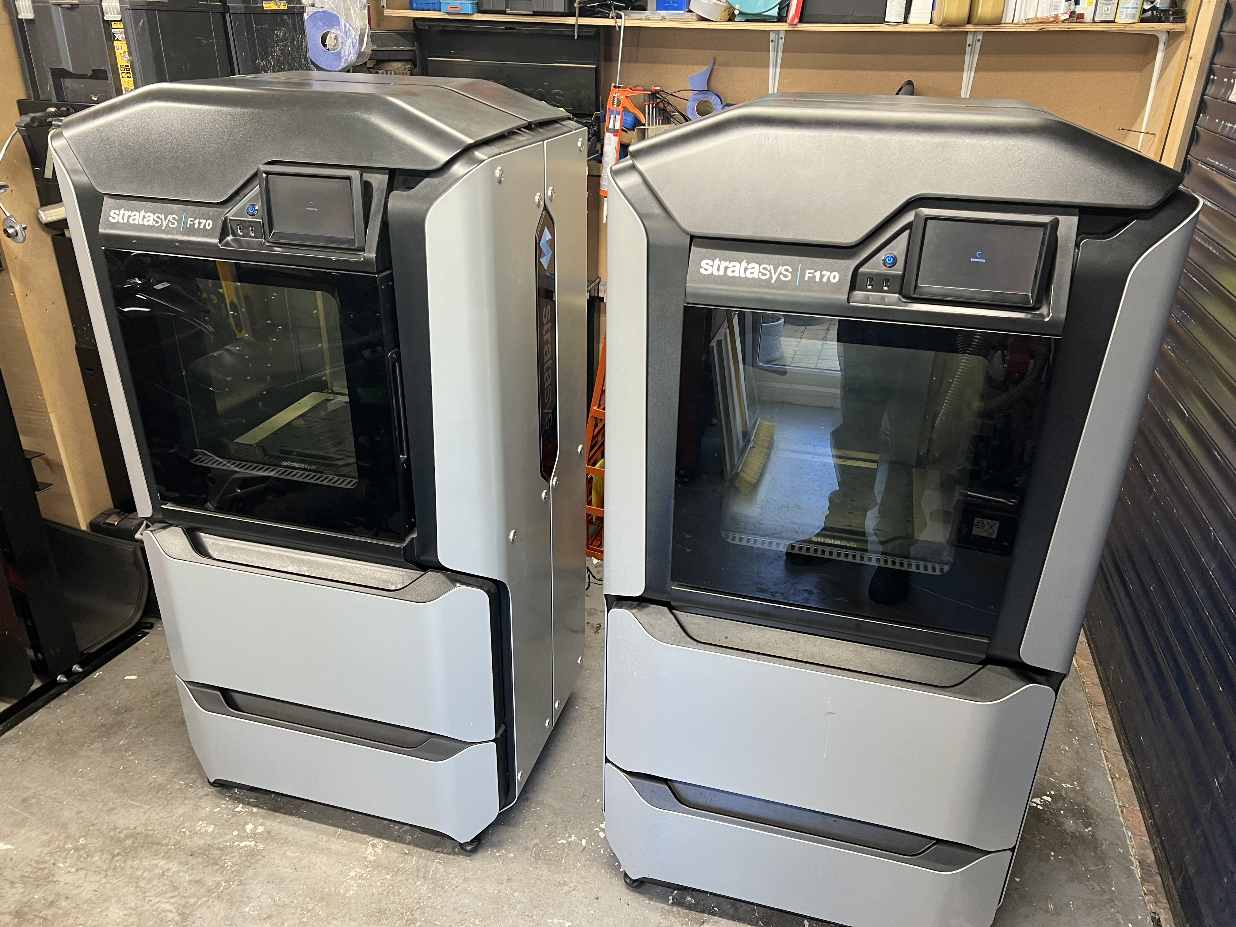
I'm calling the £50 machine P1 and the working machine P2. P1 was collected on 14 October. With the rear cover off, the heater/power control board immediately became interesting. The close-ups below show why.
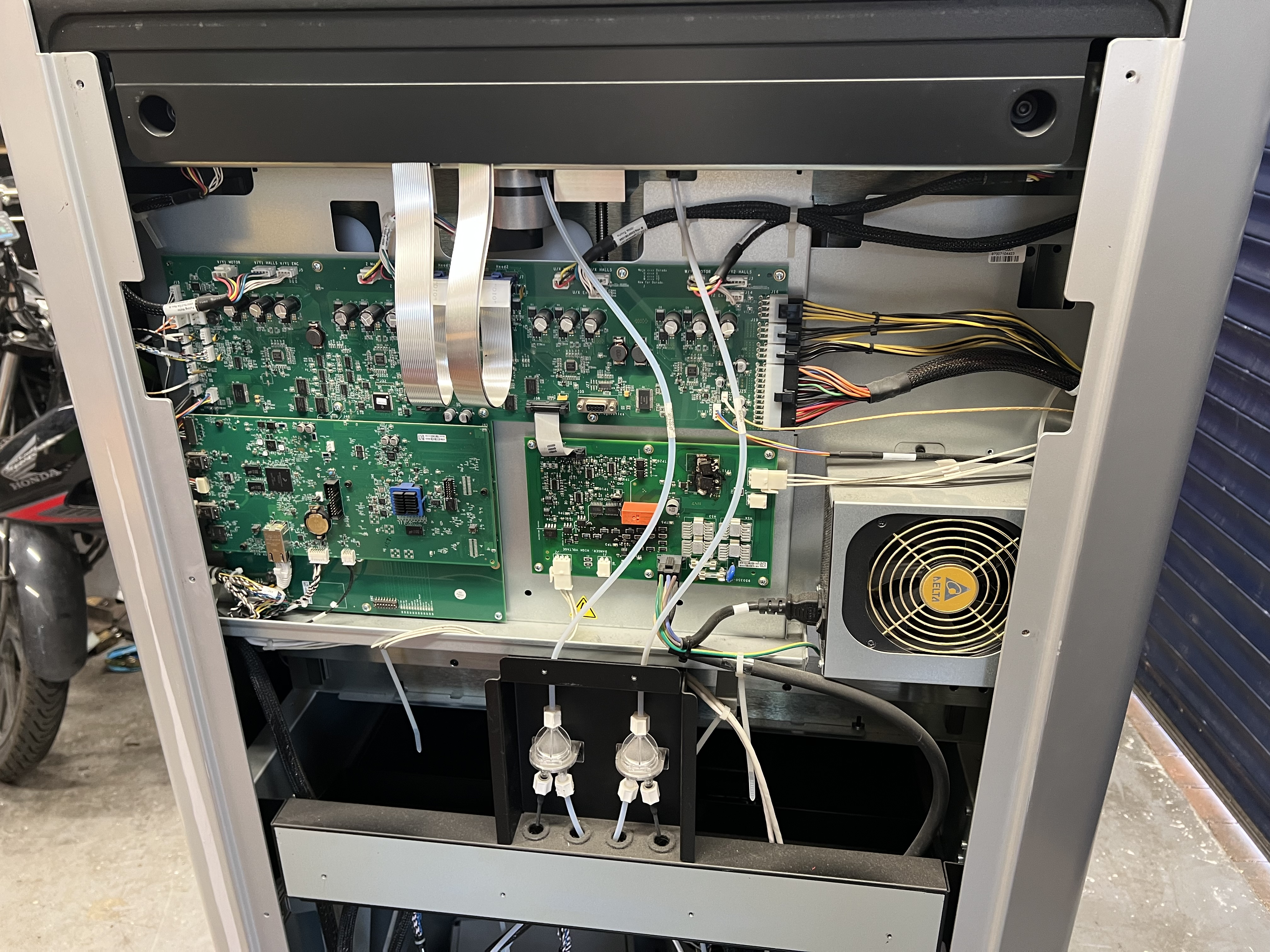
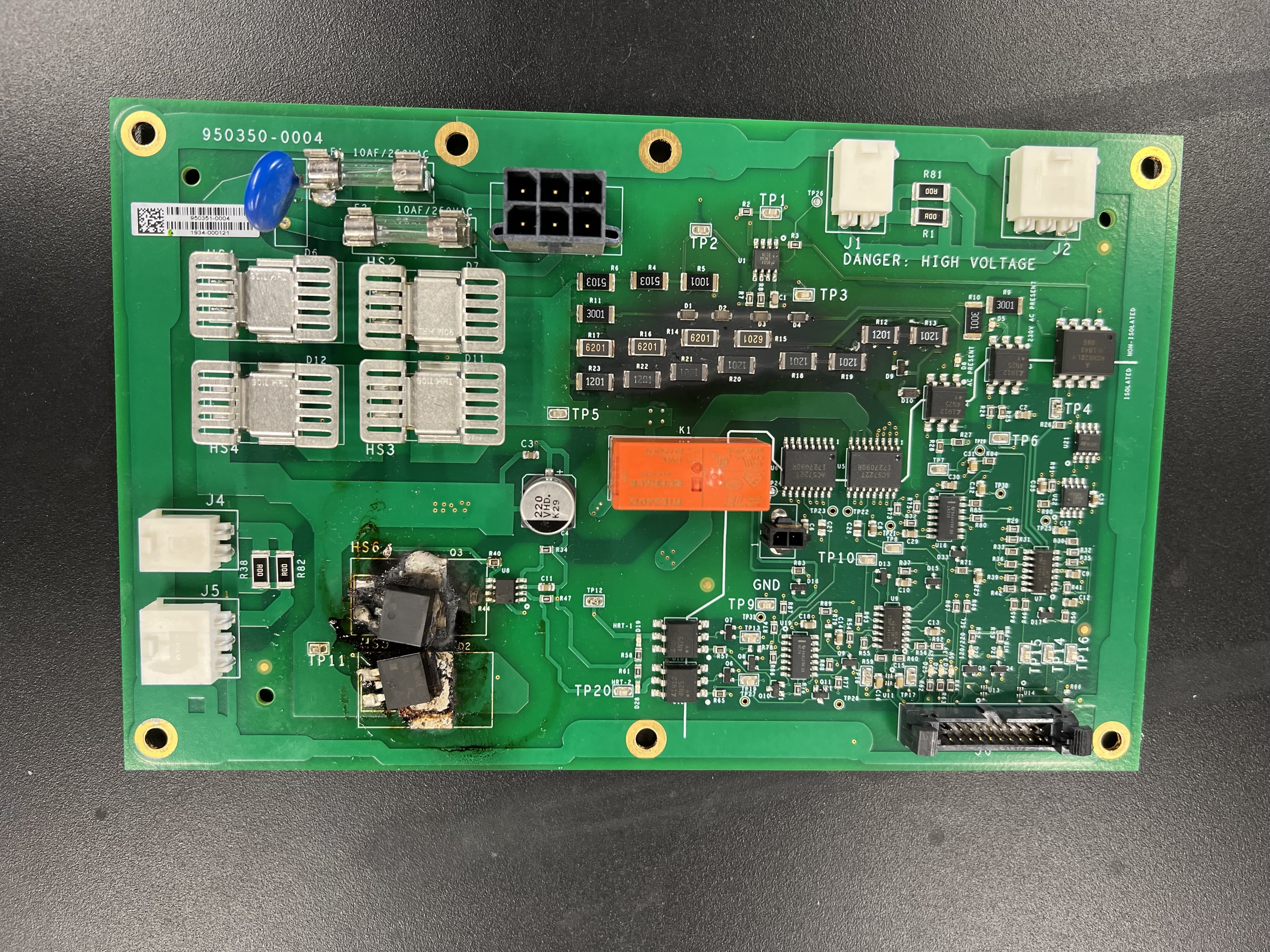
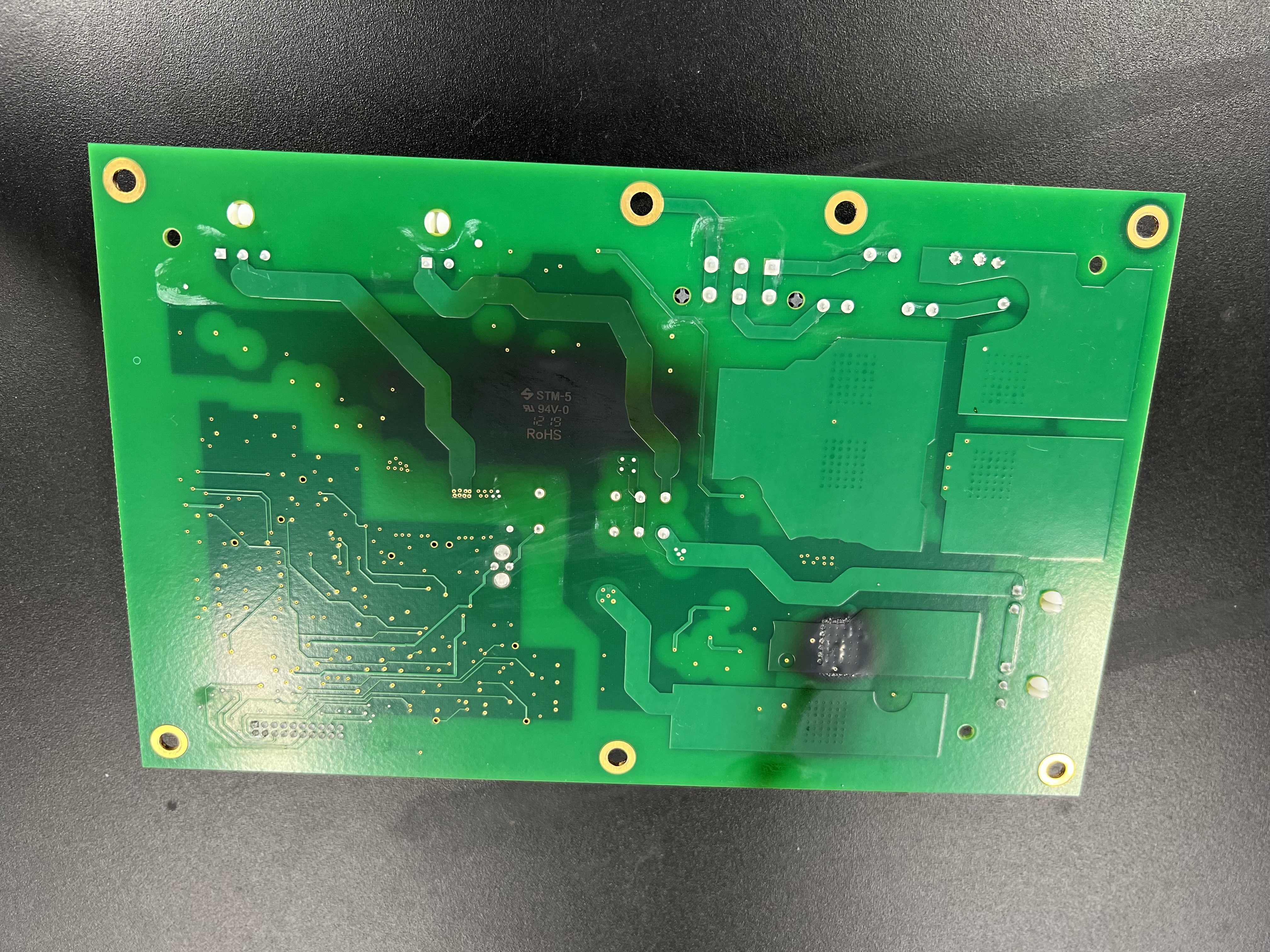
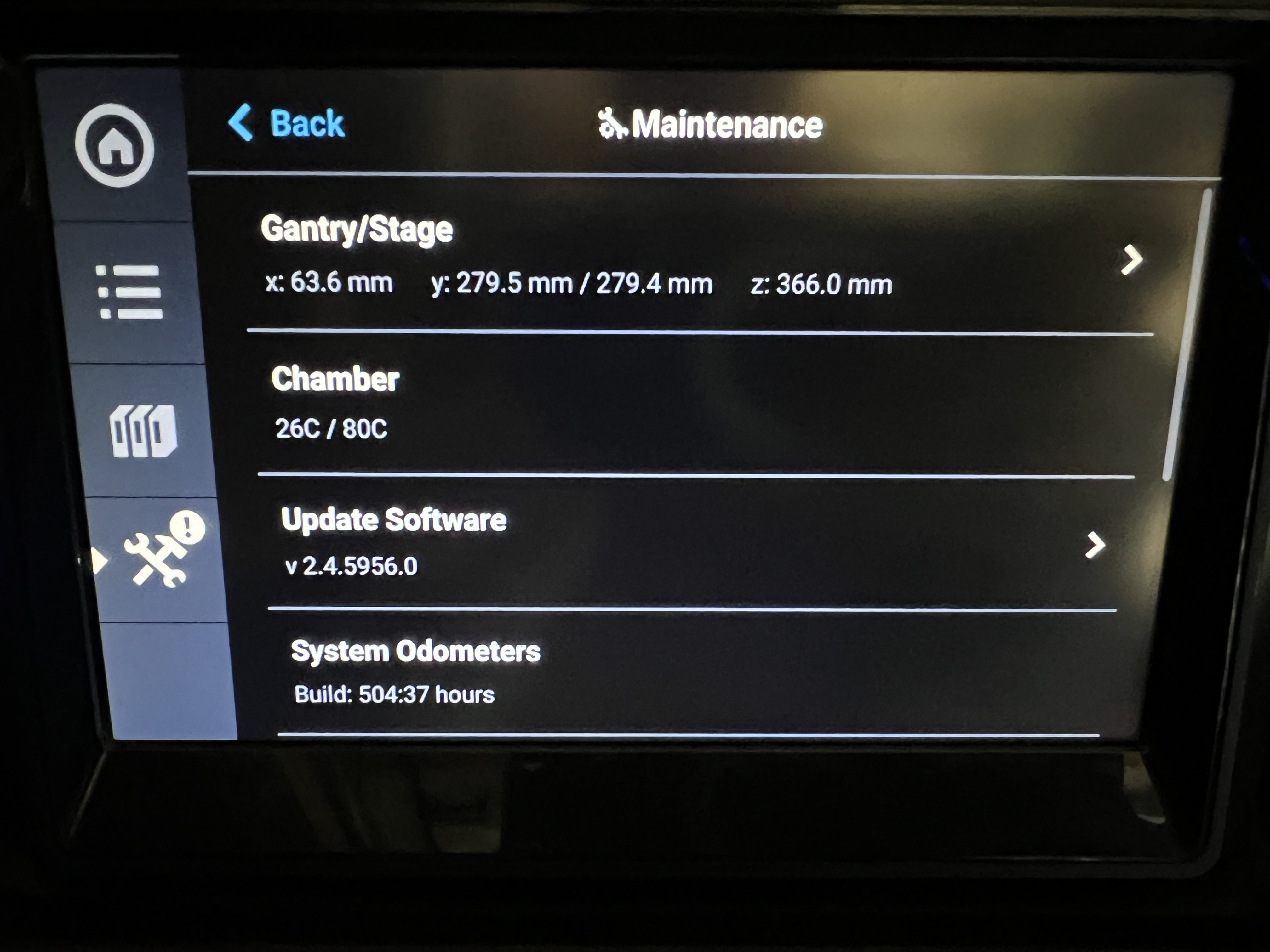
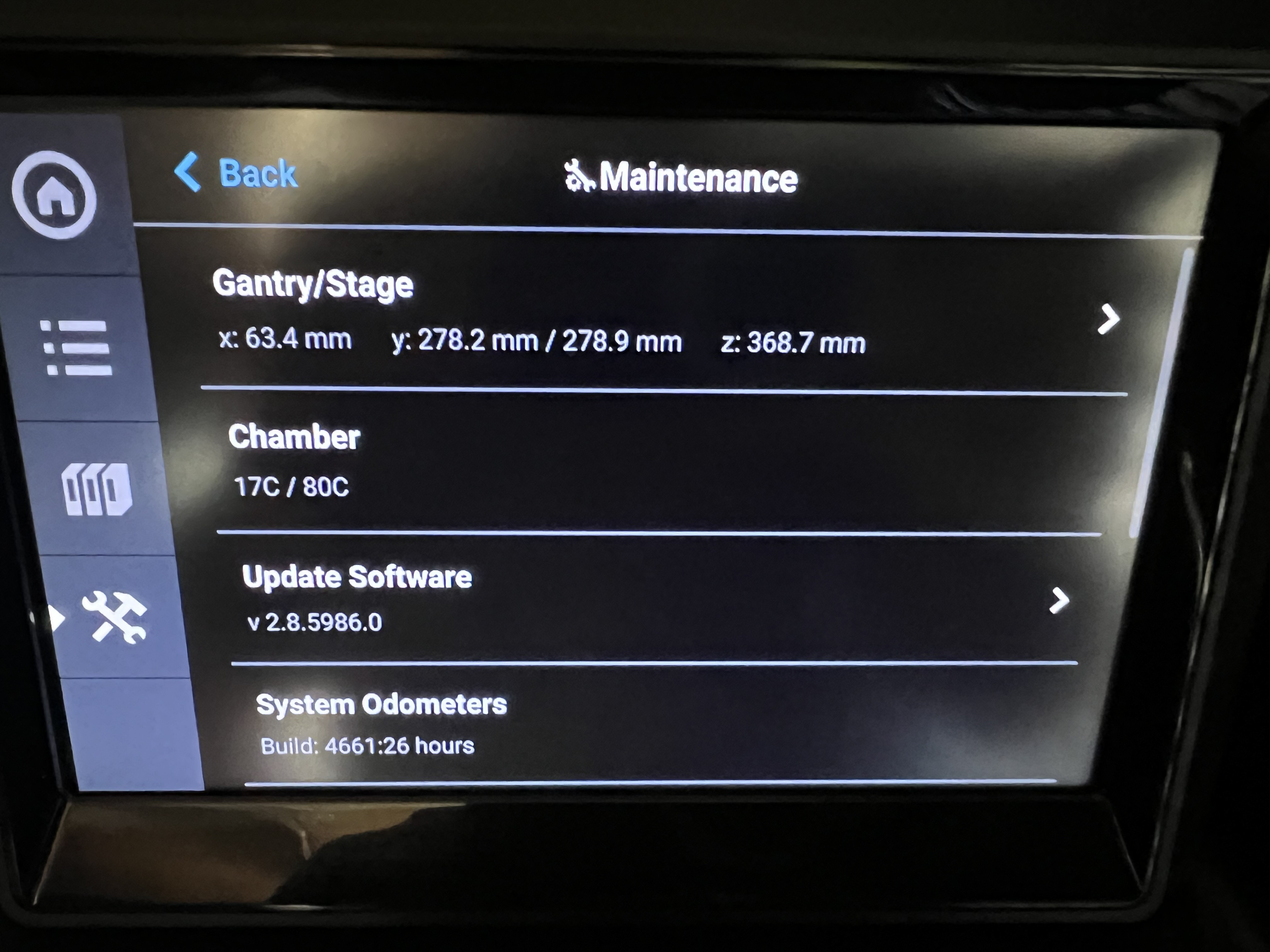
The build counters add another small detail: P1 shows 504:37 hours, P2 shows 4661:26. The cheaper machine has done far fewer build hours.
Two identical heads, two nozzle heights.
A closer look at P1 turned up a useful detail: the model and support heads are identical, right down to the part number, 950957-0005. The difference is in how the carriage positions them.
Running the carriage into its stops actuates the lift for the right-hand support head. Raised, its nozzle sits about 1.5–2 mm above the model nozzle. Actuate it the other way and the tops of the heads look level, but underneath, the support nozzle is about 1 mm lower than the model nozzle. That suggests the support head has a slightly lower mounting position in the carriage.
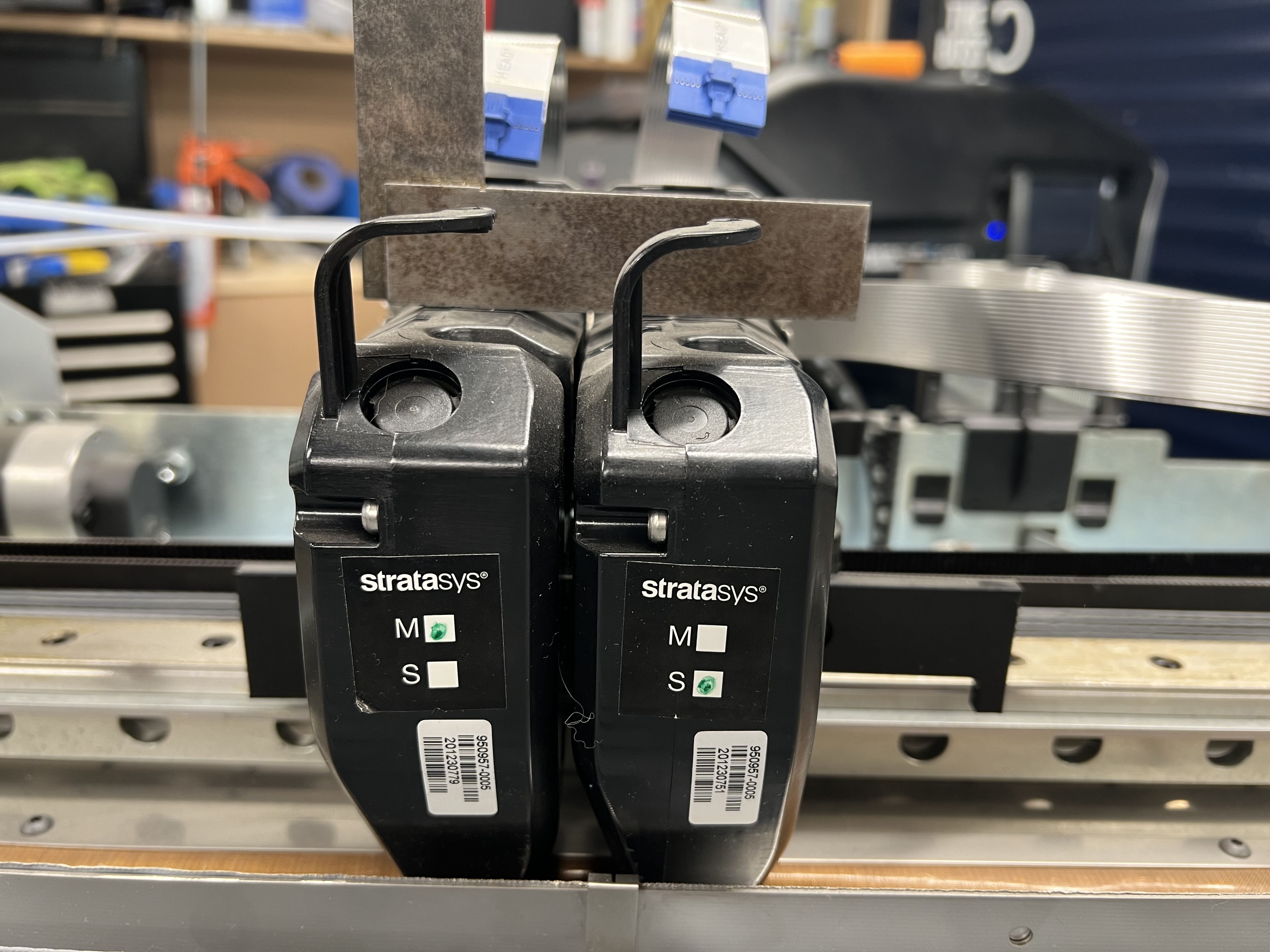
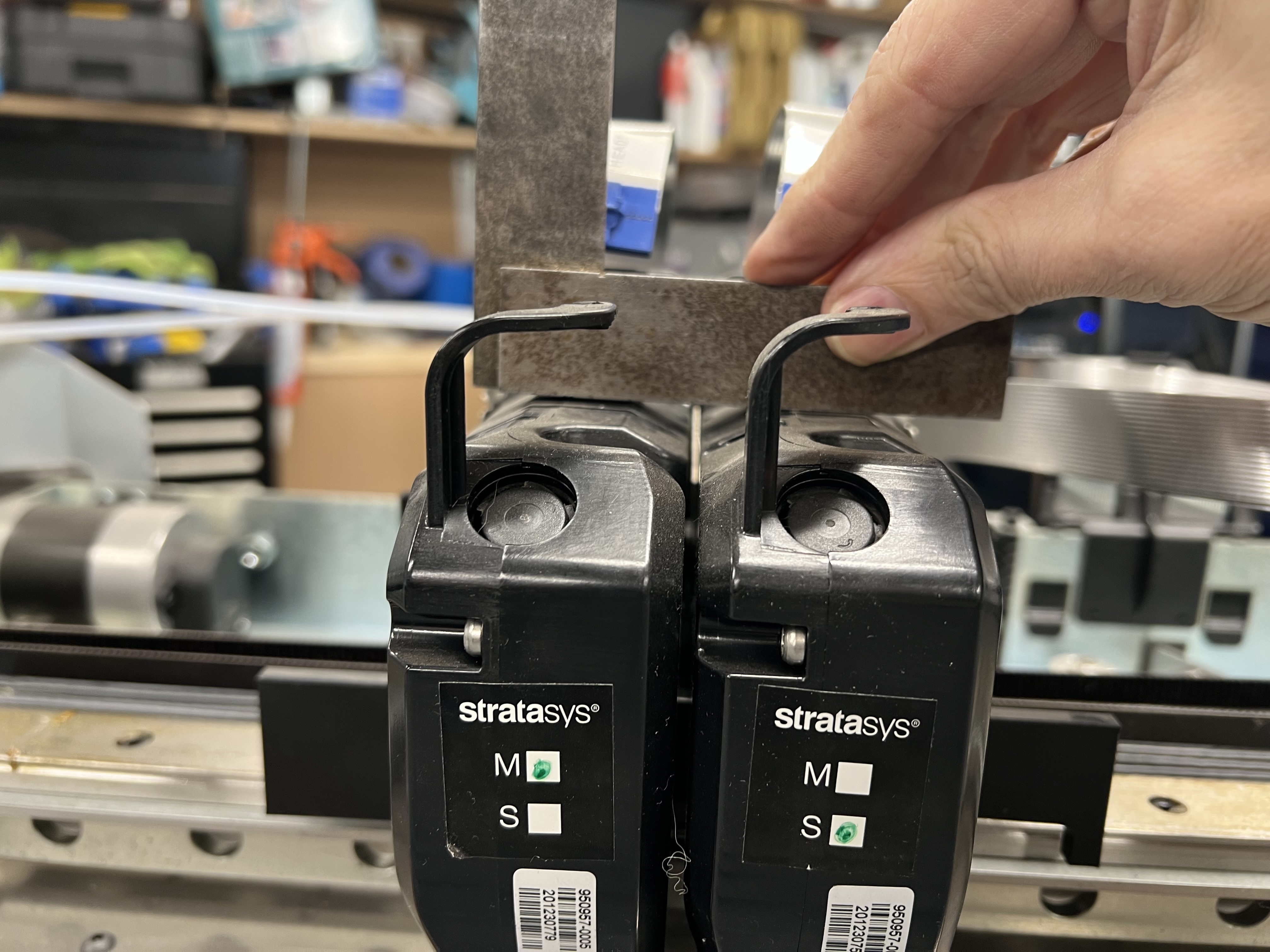
With the heads out, both bays appear to be independent aluminium platens, spring-loaded at the rear, with what looks like a rubber washer or grommet in the centre. Both can pivot upwards at the front. Normally the model head stays down while the support head is raised or lowered.
That movement gives me an interesting possibility for nozzle-contact sensing. There is room underneath the front of each platen for a switch. Touch the nozzle to the bed, let the front of the platen lift and use the switch to detect contact. Each nozzle could then establish its own Z-height offset using its existing mount.
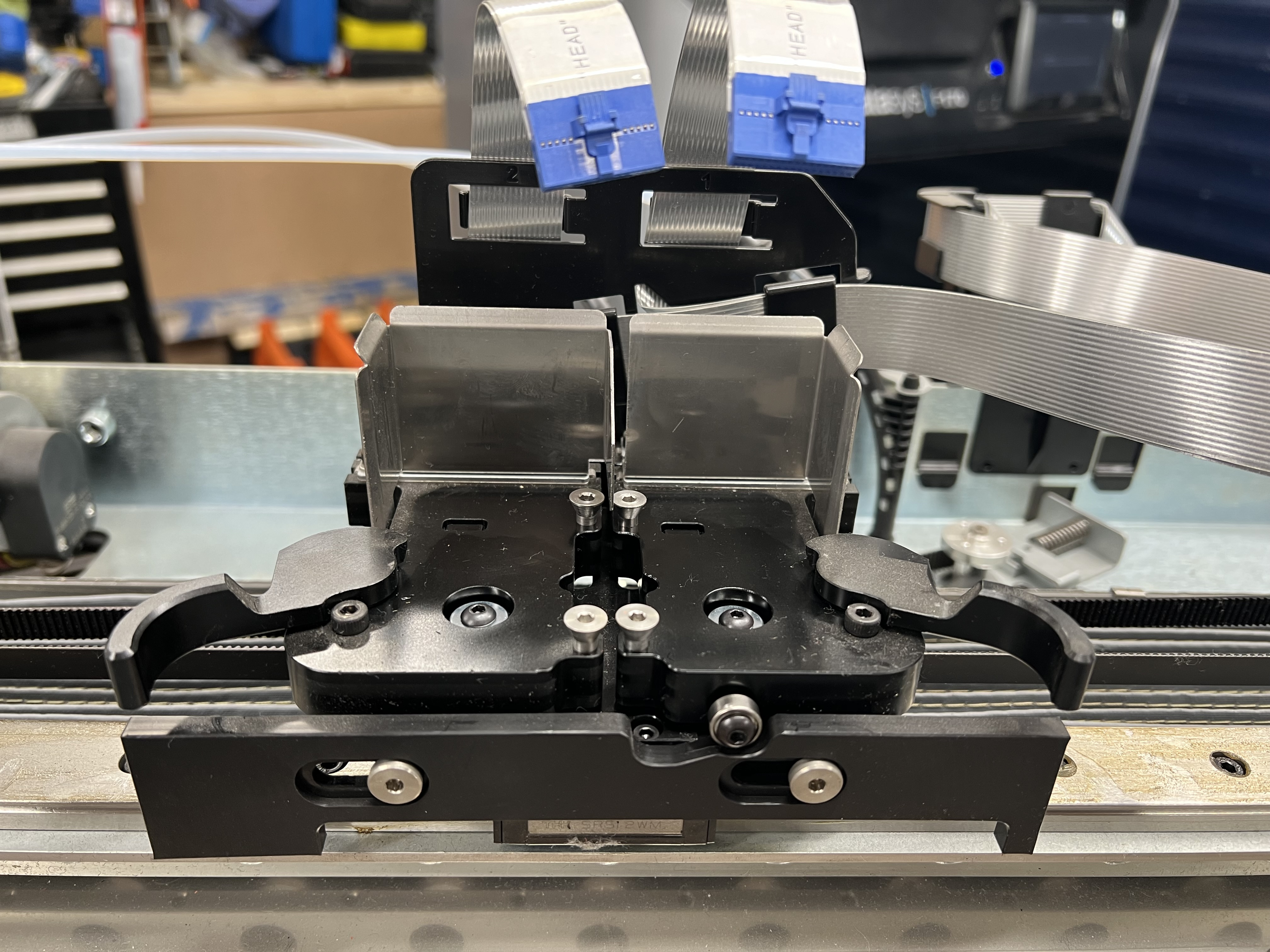
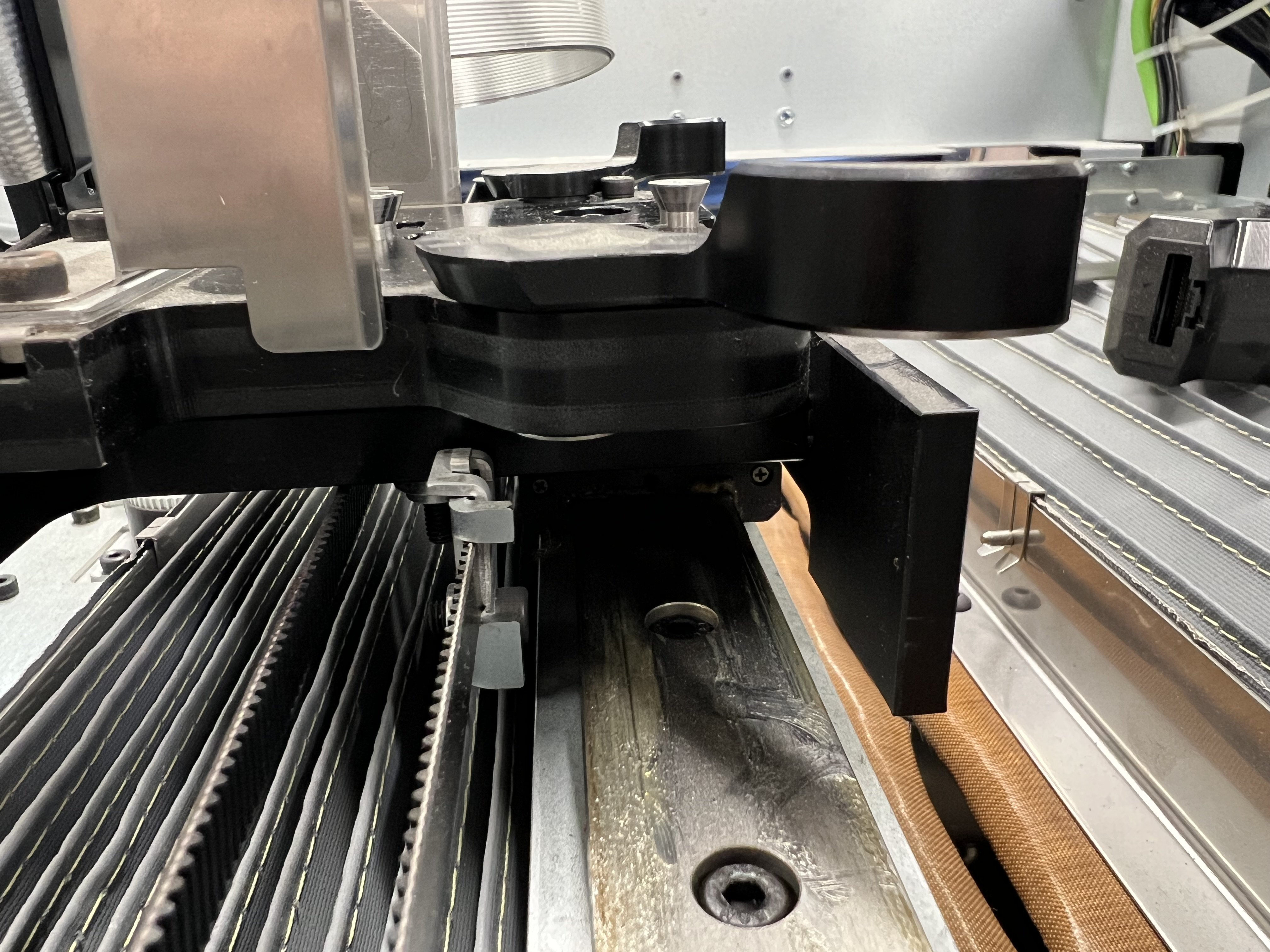
I've measured roughly 410 × 300 mm of available area. Keeping the dual-nozzle arrangement takes about 50 mm off the width. I'd use the second nozzle for support material, and retaining this carriage gives me both the lift and a possible route to contact sensing.
An oven inside the covers.
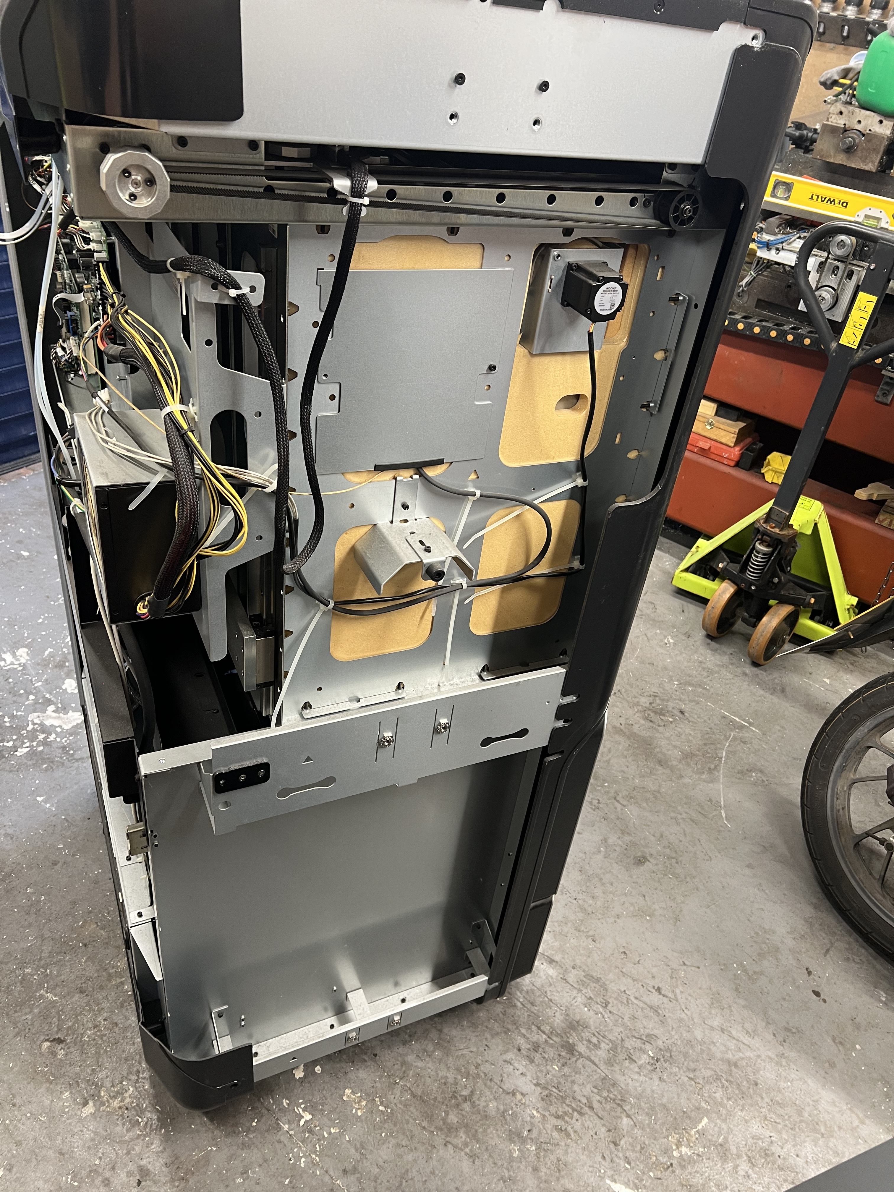
Taking the panels off makes the construction much easier to appreciate. The steel-lined chamber has its own insulation, with the heater blower motors mounted outside it. The plastic bodywork is another layer around that assembly.
A closer look at the door
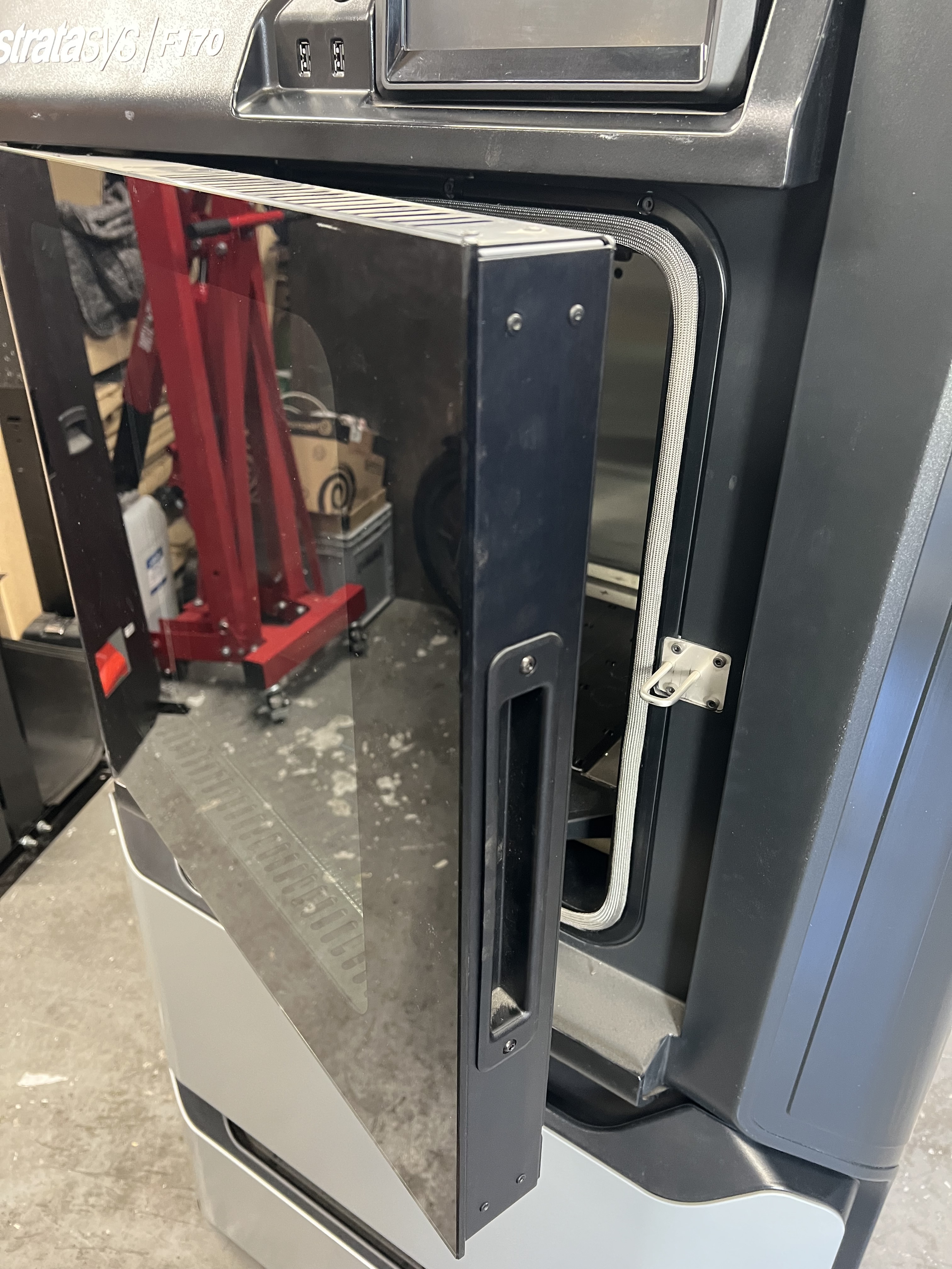
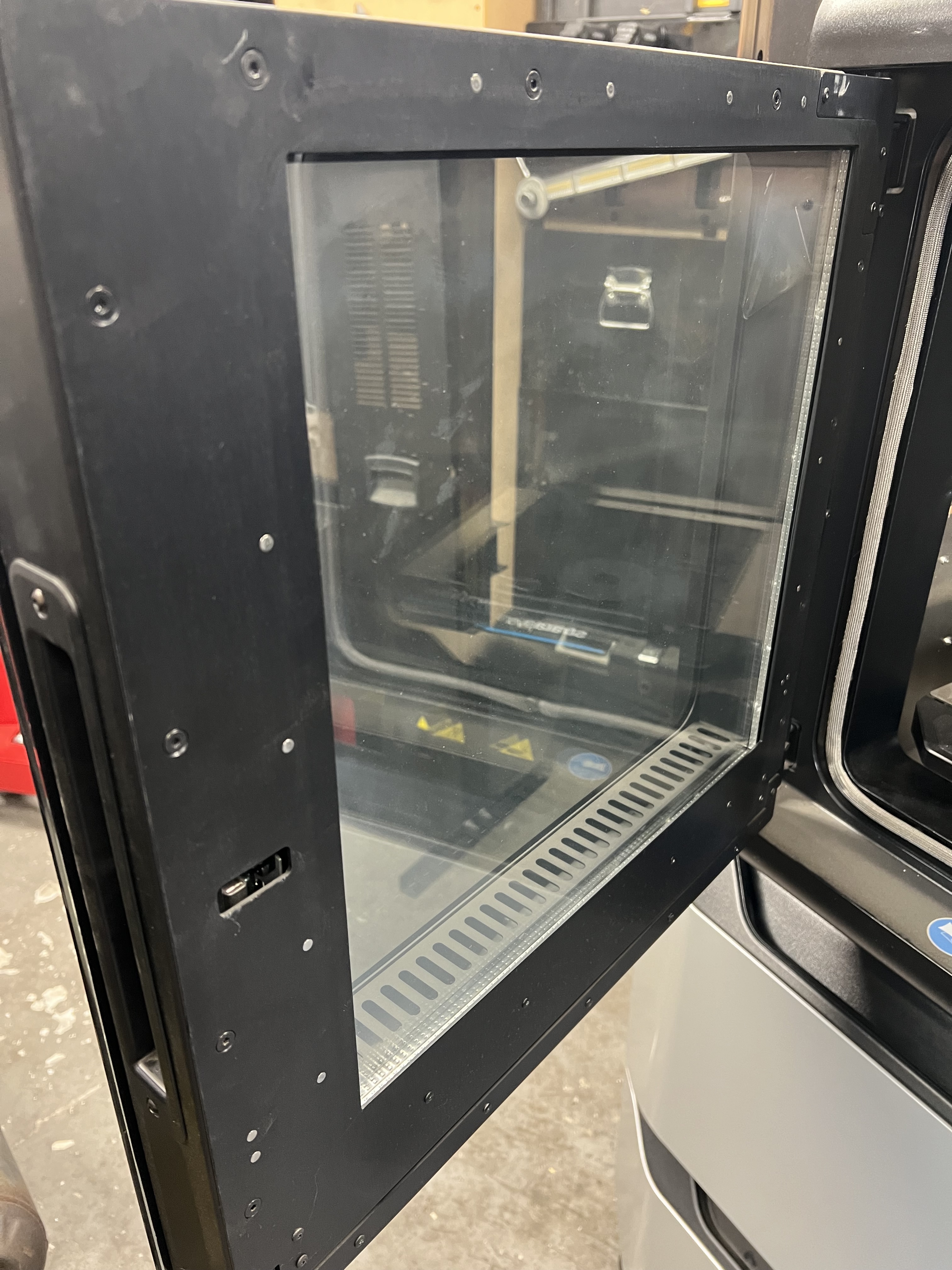
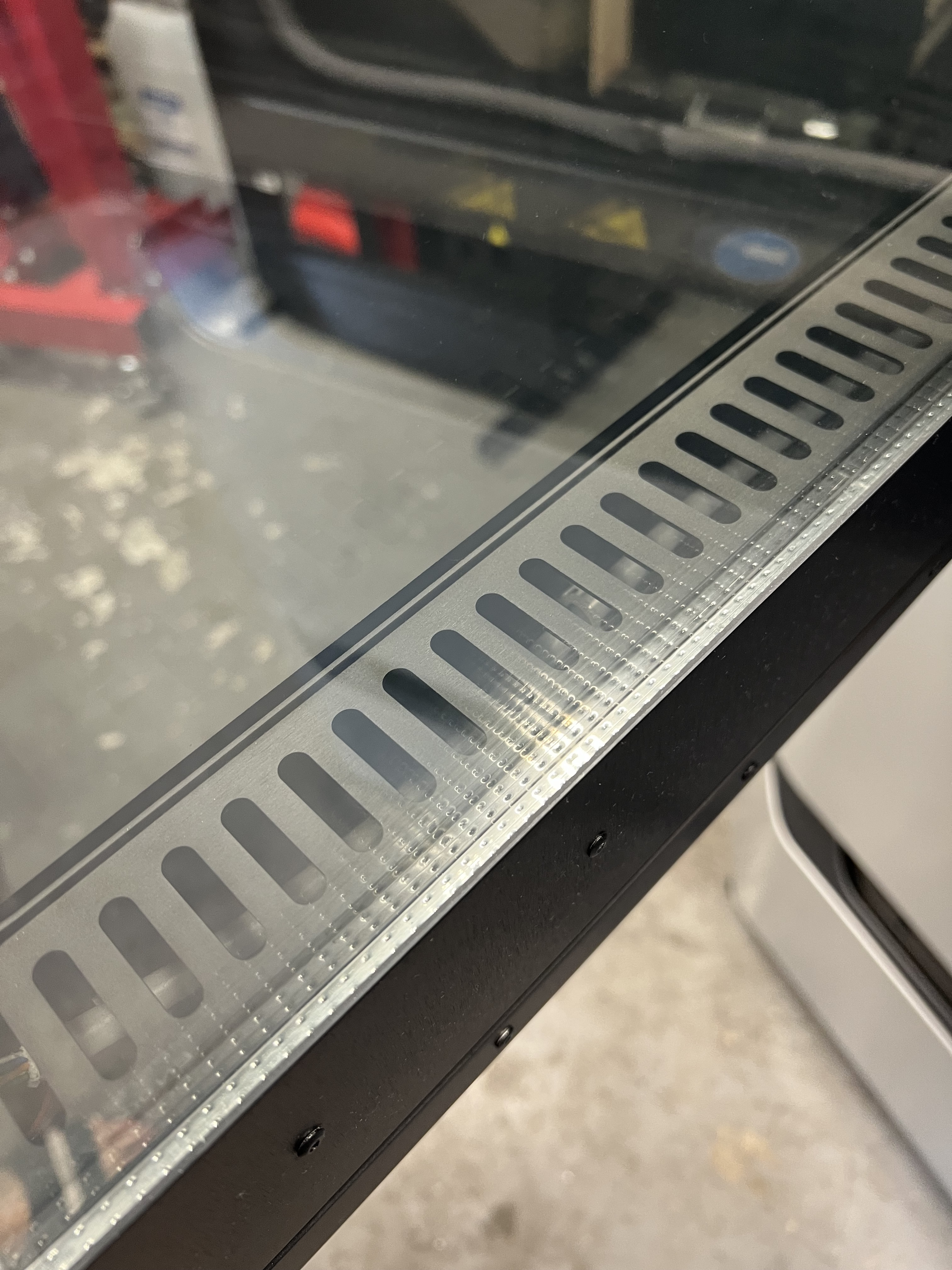
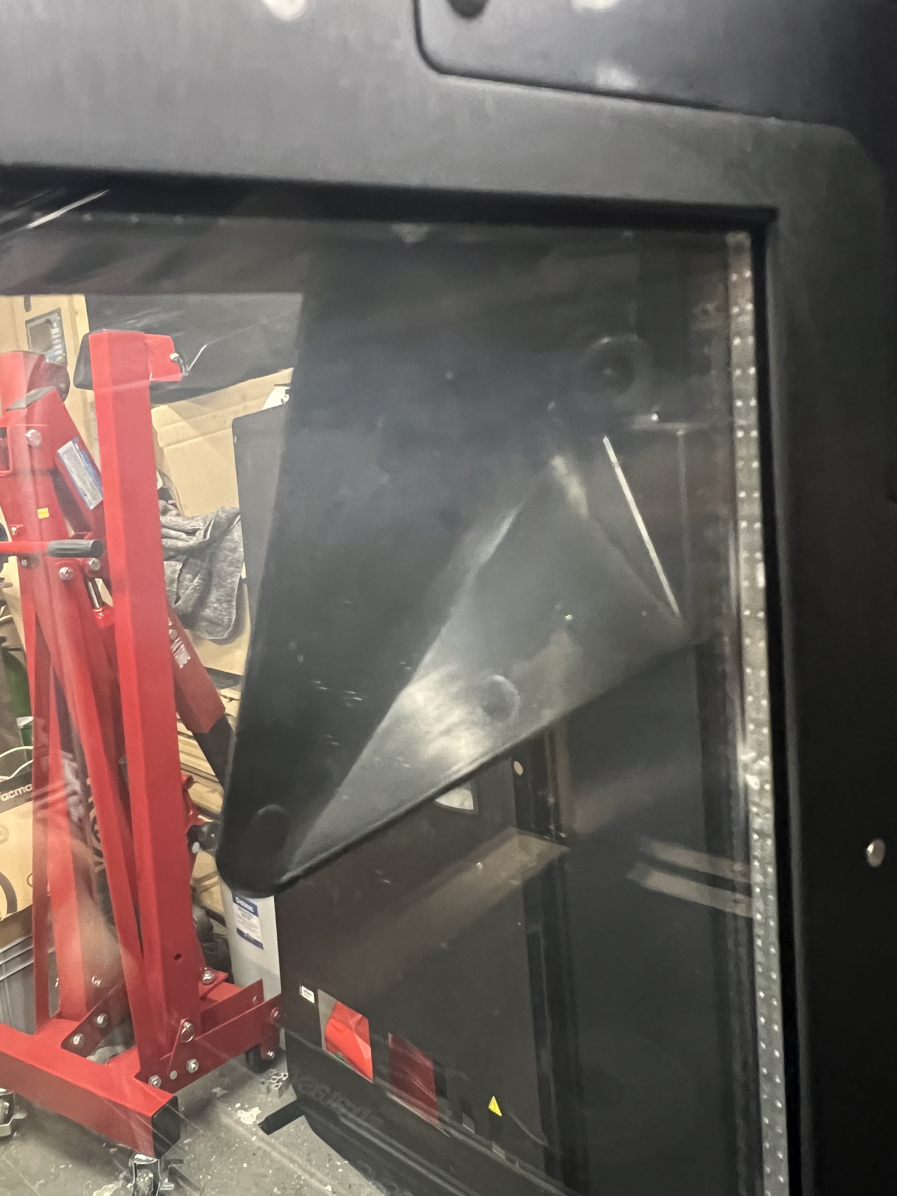
The two door views below show more than a single pane of glass. There is an internal double-glazed window as well as the external high-temperature glass. The camera is tucked into the door structure too, insulated from the chamber rather than hanging inside the oven.
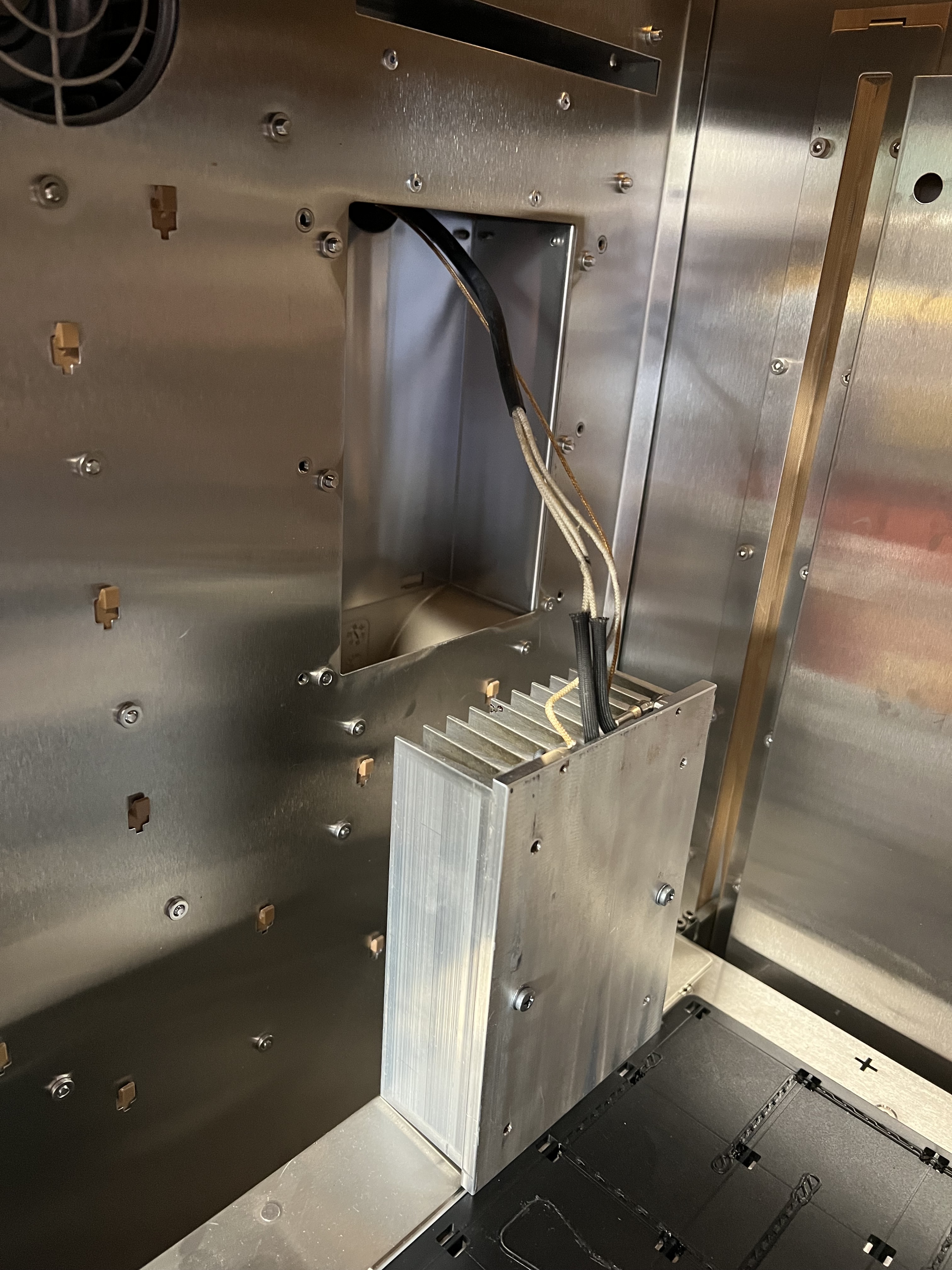
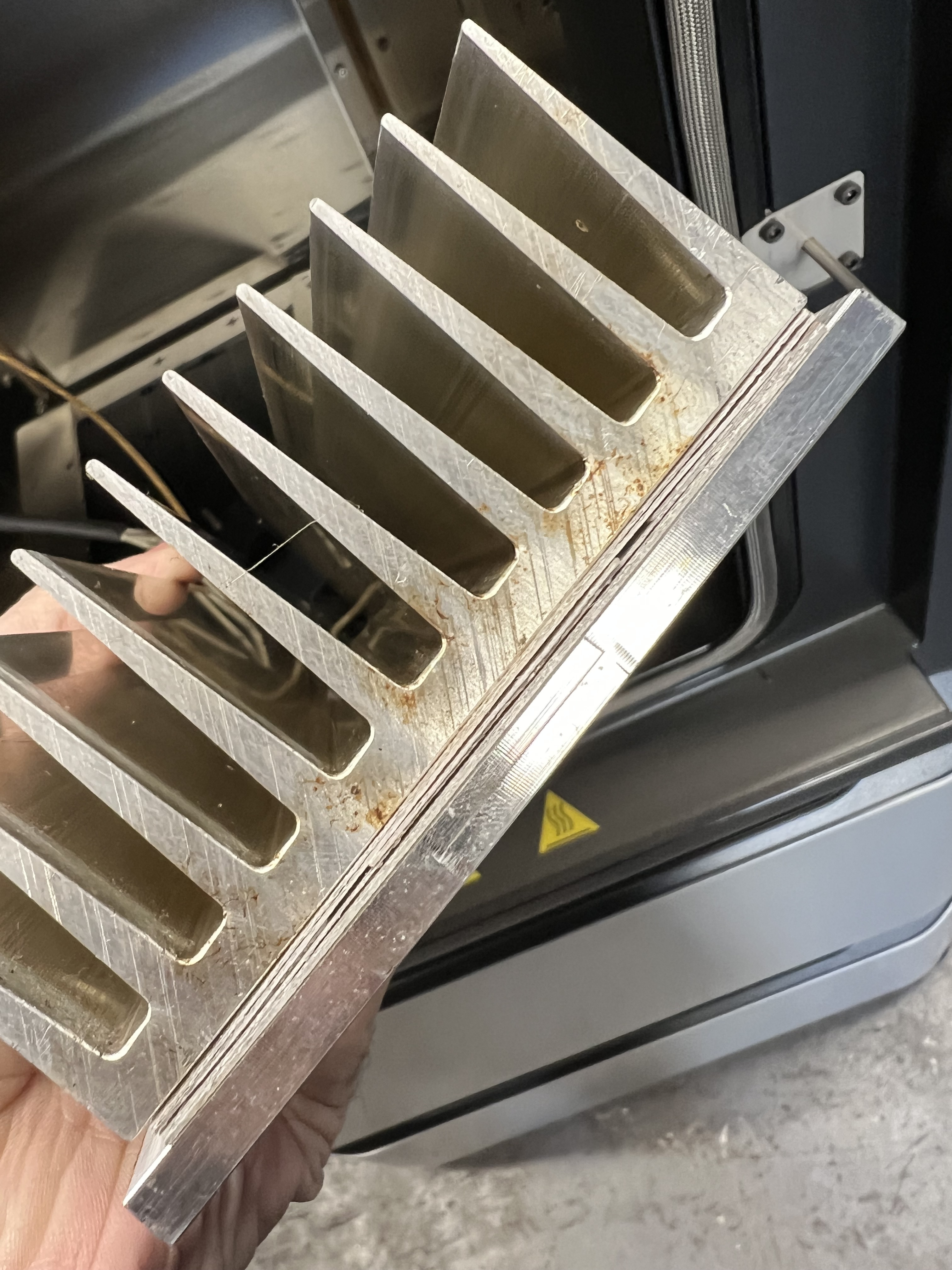
Mica heaters and brushless blowers
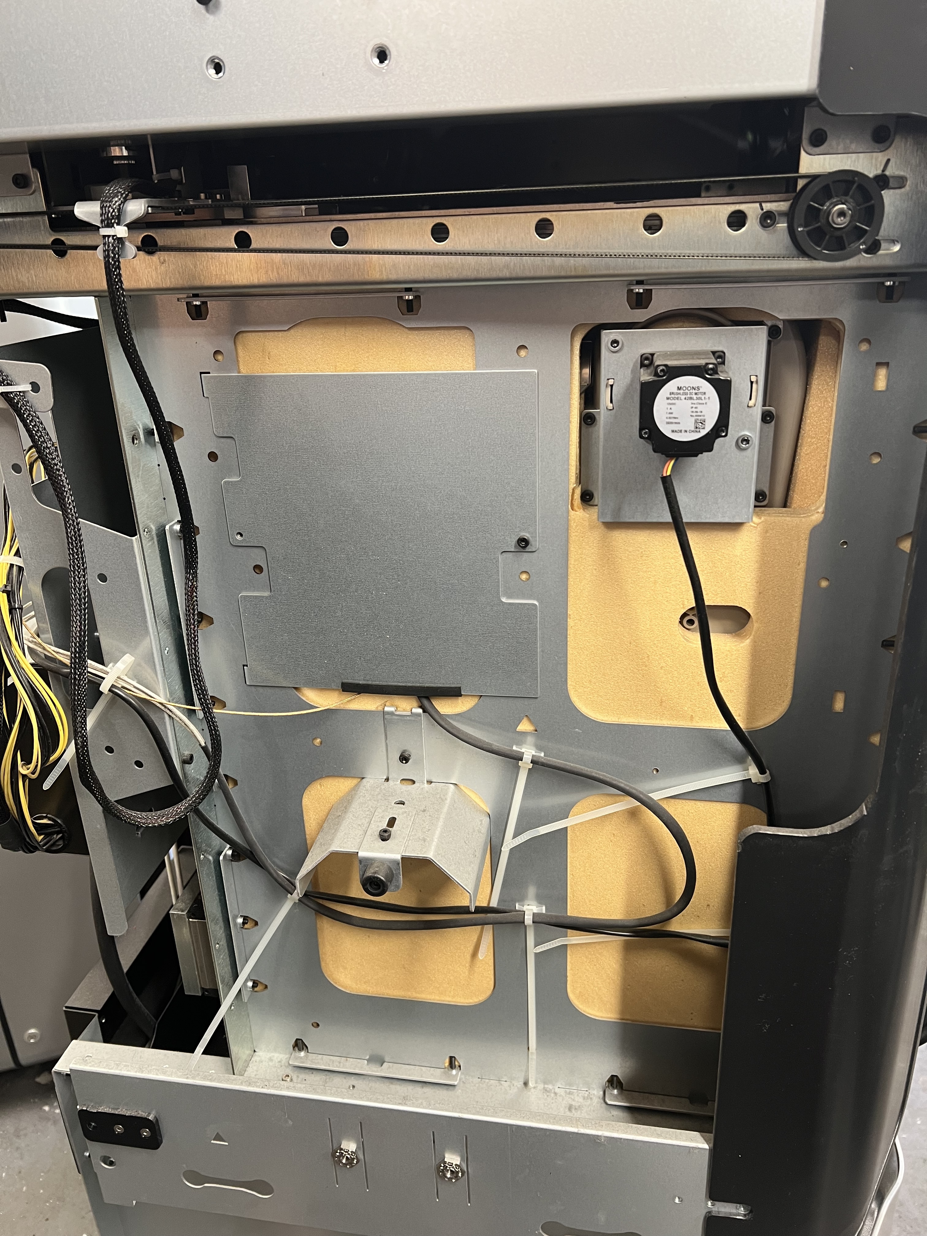
With the heater pulled out, the fins and layered mica construction are exposed. On the other side of the chamber insulation sit the two brushless heater blower motors.
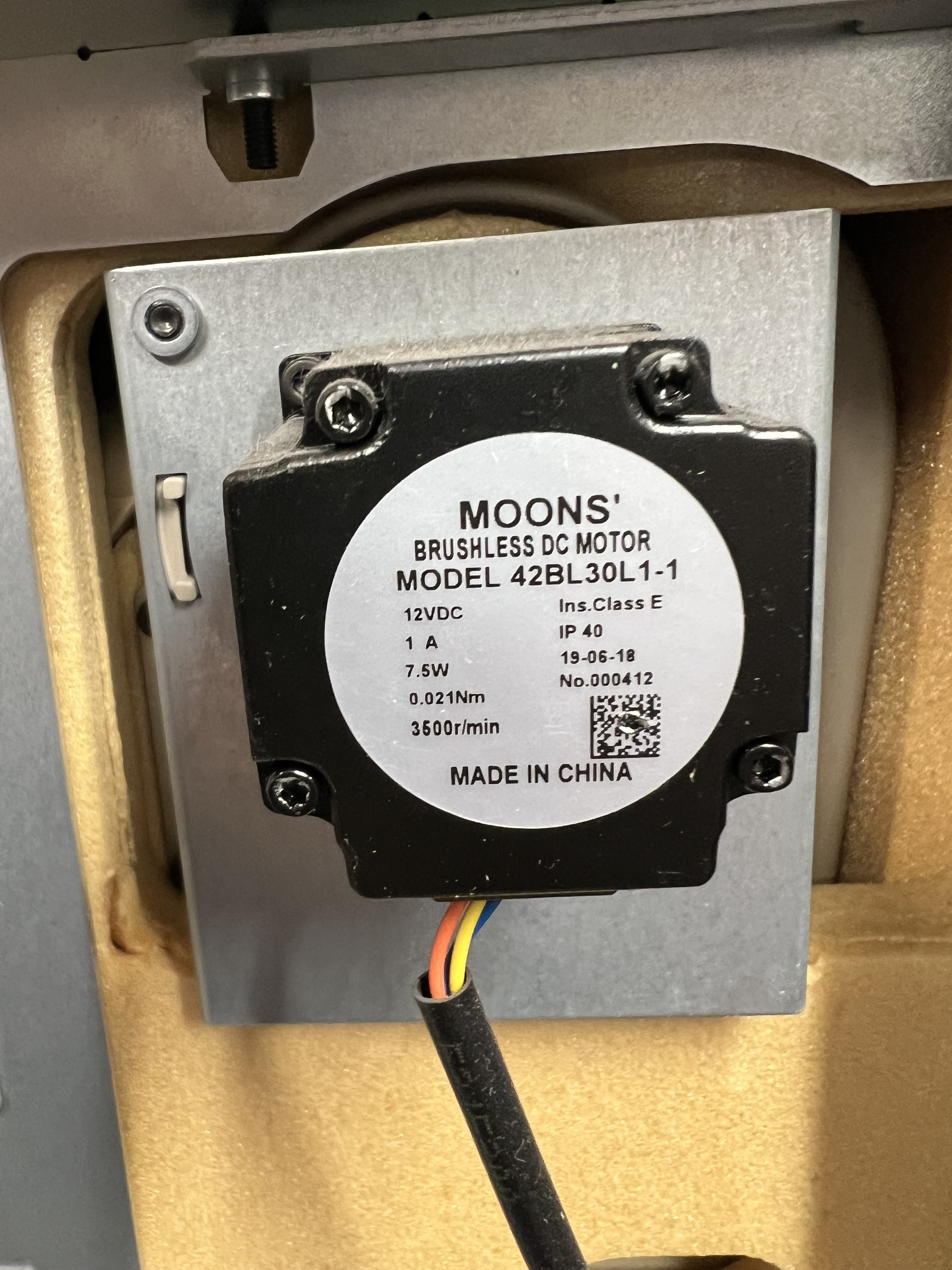
The motor label reads MOONS’ 42BL30L1-1: 12 V DC, 1 A, 7.5 W, 0.021 Nm and 3,500 rpm, with Class E insulation and an IP40 rating. MOONS’ publishes a reference for the related S42 motor range; the ratings here are from the fitted motor’s label.
More workshop photographs: covers and their removal · the internals.
Where the heat gets to.
While P2 was preheating and stabilising its chamber for automatic tip calibration, I took some readings with an infrared thermometer. The printer didn't show a temperature during the procedure, and opening either the door or the lid would stop it, so I started with the outside.
| Location | IR reading |
|---|---|
| Top of the cowling | Just under 29°C |
| Front oven door | 19.6°C |
| Side panel | 19.7°C |
The cowling appeared to be the warmest external spot. After opening the chamber, I worked around the shield, head and motion hardware.
| Location | IR reading |
|---|---|
| Top heat shield | 65°C |
| Top of a print head | 39°C |
| Inside the chamber | Just under 80°C |
| Rear steel above the heat shield | 30°C |
| X rail | 35.5°C |
| X motor | 31.6°C |
| One Y rail | 38.3°C |
The shield was at 65°C while the X motor was at 31.6°C and the rails were in the thirties. This is the part of the F170's construction that appealed to me in the first place: an oven for the print, with the motion system sitting above it.
The start of a Plan
The machine I want to build has a chamber up to 120°C, a heated bed up to 200°C and a 500°C-capable hotend assembly. PA, PPA, PPS and PC are the main attraction, filled and unfilled. PEI and PEEK are interesting too, but they're not the reason I bought these machines.
I'm leaning towards RepRapFirmware on a Duet 3, keeping the original motors if I can. That might turn into a custom 6p BLDC motor-driver project of its own. The original Stratasys drives would come out, while the motors and feedback stay with the mechanics.
For the printhead, I'd like a new assembly that fits the existing carriage and makes use of its quick-release mounting and nozzle lift. The LDO Orbiter 2.5 and Bondtech LGX are the extruders currently in the frame. For hotends, I'm looking at the Phaetus Dragon UHF or a Mosquito. Those are the starting candidates; the carriage and the reach through the heat shield will have a say in the choice.
The bed will be a new heated aluminium tooling plate, replacing the original build platform. Taken together, that's the outline: open controls, as much of the original motion system as I can retain, new extrusion hardware, and a heated bed inside the Stratasys oven.